| Symptom of malfunction |
|
| Output limit, etc. | Without |
| Malfunction indicator light | Light out |
| Multi information | Engine system failure |
| Possible cause of malfunction | Malfunction of engine sub revolution sensor |
| Symptom of malfunction |
|
| Output limit, etc. | Without |
| Malfunction indicator light | Light out |
| Multi information | Engine system failure |
| Possible cause of malfunction | Malfunction of engine sub revolution sensor |
Detail
- Set the starter key to the "LOCK" position and connect the signal check harness.
- Disconnect the engine sub revolution sensor connector.
- Turn the starter key "ON" and measure voltage between the 3rd and 2nd terminals of the engine sub revolution sensor connector (vehicle harness side).
NO
Go to [2] Measuring voltage between terminals.
YES
Go to [3] Measuring an input waveform of the engine ECU.
Detail
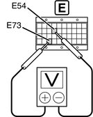
- Measure voltage between the terminals E73 and E54.

ECU terminal No. Description of terminal
Standard value: 4.5-5.5 V
NO
Fault in engine ECU and/or connectorsYES
Faulty harness
Detail
- Set the starter key to the "LOCK" position and connect the engine sub revolution sensor connector.
- Start and then idle the engine.
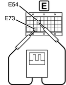
- Measure voltage between the terminals E54 and E73.

ECU terminal No. Description of terminal
NO
Go to [4] Measuring resistance between terminals.YES
Fault in engine ECU and/or ECU connectors
Detail
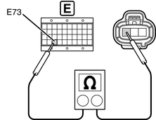
- Keep the engine sub revolution sensor connector connected.
- Measure resistance between the terminal E73 and the 1st terminal of the engine sub revolution sensor connector (vehicle harness side).


Standard value: 2 Ω or less
NO
Faulty harnessYES
Fault in engine sub revolution sensor
Detail
- Confirm the DTC P0340 is inactive
- Start the engine and let it idling condition.
- Verify the DTC P0340 is inactive.
- DTC Clear
- Clear the DTC with Hino DX
- Confirm the same DTC is not reoccurred

- P0340 is reoccur: Return to first process
- Other DTC appear: Refer to concerned Trouble shooting
Complete